High Performance Concrete (HPC)

High Performance Concrete (HPC)

High Performance Concrete (HPC)
 

High-Performance Concrete (HPC)

➤ The Performance Requirements of Hardened concrete or high-performance concrete are more or less well defined With respect to Shape, finish, strength, durability, shrinkage, and creep,
➤To achieve these objectives economically, the fresh concrete in addition to having a suitable composition in terms of quality and quantity of the materials should satisfy a number of requirements from the mixing stage till it is transported, placed in a framework and compacted,
 

Definition of high performance concrete➤

➤ High-performance concrete (HPC) can be defined as concrete that possesses high strength, work-ability, density, low permeability and resistance to chemical attack,
HPC is concrete that has been designed to be more durable and if necessary stronger than conventional concrete,
 

Introduction of high performance concrete➤

➤Deterioration, long term poor performance, and inadequate resistance to hostile environment led to the accelerated research into microstructure of concrete and hence the evaluation of high-performance concrete,
➤ Long-term performance of structures has become vital to the economics of a nation,
➤As a result, new materials and composites have been developed,
➤Today concrete structures with high compressive strength of 140 MPa are being built in United States and Europe,
 

Benefits for the designer➤

➤ The benefits of high-performance concrete to the designers are much more than those of high-strength concrete,
➤Designers can design smaller cross-sections,
➤Slender members,
➤High Elastic modulus,
➤Initial high early strength,
➤Rapid attainment of final creep level,
 

Benefits for the producer of high-performance concrete➤

 
➤In the Production of high-performance concrete Quality control in terms of raw materials and finished products is imperative,
➤Increased quality control leads to increased profitability and productivity of usual concrete,
How is high-performance concrete made?

Mechanism of high performance concrete➤

Under compressive loads, failure in normal concrete occurs either➯
 
➱Within the hydrated cement paste,
➱Along the interface between the cement paste and aggregate particle,
➱Aggregate,
 
To improve the strength and other properties it is necessary to strengthen these weak areas,
 

Improving the strength of hydrated cement paste can be done by➮ 

➤Reducing the water binder ratio and hence the usage of super plasticizing admixtures having high range water reduction capacity,
➤Using supplementary Cementitious materials,
 

Increasing the strength of the transition zone➮

➤Reducing water and cement ratio.
➤Using supplementary cementitious materials.
➤Ensuring proper coating of aggregates with cement paste.
➤Use of smaller-sized aggregates leads to homogeneous distribution of water.
 

 Aggregate Failure➱

➤Due to Aggregates failure Cement paste material remains intact.
➤Failure plane propagates through the Coarse aggregate particles.
 
What are the two typical ingredients used in high performance concrete?

Ingredients of High performance concrete➤

➤Cement (O.P.C, blended Cements etc.)
➤Water,
➤Aggregates
➮Fine Aggregates
➮Coarse Aggregates
➤Admixtures
➤Supplementary Cementitious materials(Fly Ash, Silica fume, GGBS, etc.)
 

Cement➱

Cement Selection is critical to rheology and compressive strength.
 
➤Fineness of Cement
 
➮ From the Strength point of view, the finer the cement the better the concrete,
➮ From the Rheological point of view, The finer the cement the more reactive concrete,
 

Water➱

➱Chilled water is added to reduce the concrete temperature,
➱ice flakes are added as a part of mixing water,
 

Aggregate➱ 

Strength of aggregate depends on the nature of the parent rock Prepared from.
 
➱Avoid rocks with weak cleavage planes of severely weathered.
➱Fine aggregates should be rounded and uniformly graded.
 

Admixtures➱

Super plasticiser➮ 
 
➱Disperses Cement Particles within the mix.
➱Reduces the Amount of mixed water.
➱Controls the rheology of very low water/binder ratio mixtures.
➱solve slump loss problems.

Supplementary Cementitious materials➱

➱Ground Granulated blast-furnace slag.
➱Fly ash (low Calcium, high calcium).
➱Silica flume or micro silica.
➱ Natural pozzolana (meta kaolin, rice husk ash).
 

Aspects of High-performance concrete in fresh state➱

➱Batching and mixing.
➱Tests in fresh HPC concrete.
➱Placement and Compaction.
 

Batching and Mixing➱

➱Batching of individual materials must be accurate.
➱Longer mixing time is required to ensure homogeneity as the mix is usually sticky.
➱Mixing time of 90 seconds is recommended.
 

Tests on Fresh HPC Concrete➱

Following tests on fresh high-performance concrete is carried out.
 
➱Slump / Flow table 
➱Air content 
➱Temperature
➱Unit weight
➱Setting time of mix
➱Bleeding
➱Slump retention and Pump-ability 
 

Placement and compaction of High performance concrete➱

➱Concrete mix is carried from the batching plant with the help of transit mixtures.
➱Method of placing is mostly by pumping.
➱Compaction is by both External as well as internal means.
 

Test on Hardened high performance concrete➱

The following tests are carried out on hardened high-performance concrete.
 
➱Compressive strength (Cube and Cylinder)
➱Split Tensile strength.
➱Modulus of elasticity.
➱Water permeability.
➱Rapid Chloride penetration test(RCPT)
 

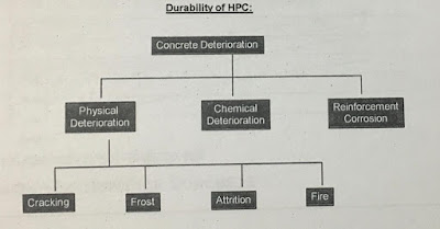
Durability of HPC➱

➱Durability of Concrete can be defined as the resistance of concrete to deteriorating influences which may be inside the concrete itself or which may be present in the environment to which it is exposed.
➱ The durability of Concrete Largely depends on the ease with which fluids, both liquids and gases, can enter into and move through the concrete. This property is known as the permeability of concrete.
High Performance Concrete (HPC)

The durability of HPC: Carbonation➱                                          ͏͏͏

➱ In Presence of Moisture CO2 Present in Air reacts with Ca(OH)2  to form CaCO3.
➱ Carbonation causes the reduction in pH of pore water from between 12.6 to 13.5 to about 9.
➱ Steel embedded in concrete forms a thin passivity layer of oxide which remains only with high pH.
➱ As The pH reduces the oxide layer is removed and the corrosion of steel starts, its volume increases and creates tensile stresses in concrete.

Durability of HPC: Chloride attack➱

➱ The primary action in chloride attack is the corrosion of steel and consequently damage to surrounding concrete.
➱ As long as the oxide film on steel is present, The steel remains intact.
➱ Chloride ions destroy the film and in the presence of water and oxygen corrosion occurs.
➱ Corrosion does not occur in dry or fully submerged concrete but occurs in alternate wetting and drying and relative humidity of 70-80 %.
➱ Chlorides can be present in concrete through the use of contaminated aggregates, seawater or chlorides in admixture.
➱ According to I.S.  total chloride content in cement should not exceed 0.05% by mass of cement.
➱ I.S. 456-2000 states that total Chloride content in concrete should not exceed .4 and .6 kg/cum for pre-stressed and reinforced/plain concrete containing embedded metal respectively.
High Performance Concrete (HPC)

Durability of HPC: Sulphate attack➱ 

➱ Common sulphates present in soil and groundwater are sodium, potassium, magnesium, and calcium.
➱ Sulphates present in solution react with hydrated cement paste.
➱ Sodium sulphate attacks Ca(OH)2 and gypsum is deposited, Ca(OH)2 Can Also be completely leached out.
➱ Magnesium sulphate attacks calcium silicate, calcium aluminate hydrates and also Ca(OH)2.
➱ Calcium sulphate attacks calcium aluminate hydrate (C3A) forming ettringite.
➱ Ettringnite formed has a higher volume and causes expansion in concrete.

Durability of HPC: Alkali Aggregate Reactivity➱

➱ Reaction between active silica constituents of aggregates and alkali in cement forms alkali-silicate gels in planes of weakness or either in pores or surface of aggregates.
➱ The reaction starts with an attack on siliceous minerals in aggregates by alkaline hydroxide in pore water derived from the alkalies(Na2O or K2O) in cement.
➱This gel is of unlimited swelling type, absorbs water and causes an increase in volume.
High Performance Concrete (HPC)

Development Of HPC Mixes➱ 

➱ Computing the Target strength.
➱ Estimating mixing water content.
➱ Calculation of water to cementitious material ratio.
➱ Selection of percentage of SCM.
➱ Selection of fine to total aggregate ratio.
➱ Calculation of aggregate contents.
➱ Selection of Superplasticiser dosage.
➱ Trial mix and testing.

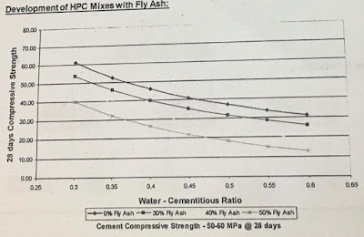
Development Of HPC Mixes with Fly Ash➱

Approx mixing water for 20 mm aggregate and 100 mm slump

Fly Ash Content  Water kg/Cum
30 155+5 or 155-5
40 150+5 or 150-5
50 145+5 or 145-5
 
➱ Selection of fine to total aggregate – Normally 25-40 % is used depending upon the grade of concrete, nominal size of aggregate and workability required.
➱ Calculate aggregate content based on the absolute volume method.
High Performance Concrete (HPC)
 
High Performance Concrete (HPC)
 

Where is high performance concrete used?
What is high performance concrete used for?

All Necessary Factors➱

 
Specifications for Bandra – Warli Sea Link Project➱
 
 ➱ Selection of water/binder ratio sufficient enough to achieve the target strength with special consideration from a durability point of view.
➱ Use of Supplementary Cementitious material together with a low water to binder ratio to make concrete structure more dense with a minimum volume of capillary pores, hence making it more durable.
➱ Water content in the mix is required to be kept at the lowest practical so as to minimize drying Shrinkage.
➱ Limiting the heat generation (especially in mass concrete) by keeping the total OPC content in the mix to the minimum required.
➱ Use of high-range water reduction admixtures to achieve the required workability.
High Performance Concrete (HPC)
Bandra-Warli Sea link under construction
High Performance Concrete (HPC)
bandra-Warli Sea link

Project Specification➯

Grade of Concrete- M60
Target Strength – 74 MPa
Max.Water / Binder ratio – < .35
Permeability – Less than 25 mm as per DIN 1048

Ingredients (Kg/cum) Earlier Mix Modified mix
Cement  320 300
Fly ash  110 (25 %) 196 (40 %)
Micro silica 43 40
Total cementitious material  473 536
total water  127 136
W/C ratio  .27 .25
Coarse aggregate  947 1077
fine aggregate 947 750
Admixture 15.1 10.9
 
Properties  Earlier Mix Modified Mix % (Modified/Earlier)
Compressive Strength (MPa)
3 days 39.8 39.3 98.7 %
7 days 56.9 54.8 96.3 %
28 days 78.1 74.7 95.6 %
56 days 79.4 80.9 101.9 %
91 days 80.9 92.2 113.9 %
 
Durability properties  Field results
Water Permeability @ 28 days NIL
RCPT @ 28 days 657 Coulombs
RCPT @ 91 days 432 Coulombs
 
High Performance Concrete (HPC)
 
for more such results click here 


Soil Nailing , Soil Nailing Technique, Types of soil nailing

Soil Nailing, Soil Nailing Technique, Types of Soil Nailing


Soil Nailing , Soil Nailing Technique, Types of soil nailing,
Soil Nailing


SOIL NAILING AND SOIL NAILING TECHNIQUE


INTRODUCTION OF SOIL NAILING➱

 
Soil
Nailing
Is a process To Make The soil or Soil fill  More Able to resist
loads (direct loads, Shear Loads Radial loads etc) Or to Make it more
stable,Soil nailing Reinforces soil hence the soil becomes more
stable,
 
Generally
Soil Nailing Technique is used in steep sloppy areas, high fill areas, High
embankment, retaining walls And other Structures where There is more chance of
failure of soil,
 
Here in
In this post we are going to describe about soil nailing process, soil nailing
technique, types of soil nailing and its applications,

How does a soil nail wall work?

SOIL NAILING PROCESS- TECHNIQUE➱


What is soil nailing technique?
In the
Process or Technique of Soil Nailing The Soil Is Reinforced With An Element
Such As Self Drilling Anchor bars or Reinforcing Bars Which Are
called Nails See in the fig. 
 
These Self
Drilling Anchor bars or Reinforcing Bars are installed into Self Drilled holes
or pre-drilled holes and after it grouted with contentious mix, 
 
These Self
Drilling Anchors or Reinforcing bars are installed at an angle of 5 to 20
degrees with vertical generally or any other angle which is specified,
 
As The
Drilling Work Proceeds,The concrete, Shotcrete or any other Drilling materials
are used on The drilled face to grout the nails, 
 
Soil Nailing , Soil Nailing Technique, Types of soil nailing,
Soil nailing Details


MACHINERY REQUIRED FOR SOIL NAILING➱

 
➤Grouting and mixing Equipments,
➮ High-speed shear Colloidal mixer, Grout pump, 
 
➤Drilling Equipment,
➮Rotary Air Flushed and water Flushed drilling machine, tricone bit , Rigid Drill Rods,
 
➤Compressor,
➤Shotcreting  Or Guniting Equipment,
 

MATERIALS REQUIRED FOR SOIL NAILING➱

 
➤Reinforcing Steel Rods Or Nails,
➤Self drilling anchor(SDA) bars,
Soil Nailing , Soil Nailing Technique, Types of soil nailing
Self Drilling Anchor
 
➤Shotcrete, Concrete or Any other grouting material,
➤Grout mix, 
 

ORIGIN
OF SOIL NAILING TECHNIQUE➱

 
➤The
soil nailing technique was first time implemented in France near Versailles for
a Railroad widening Project in 1972,
Soil Nailing , Soil Nailing Technique, Types of soil nailing
Soil nailing
 
➤The soil nailing Technique in United States was used first time for the support of a
13.7-metre deep foundation excavation in dense silty sand in 1976,
 

TYPES OF SOIL NAILING -METHODS➱


How do you install soil nails?

Following
Are the Various Types of Soil Nailing Methods or process,
Soil Nailing , Soil Nailing Technique, Types of soil nailing
Inserting nails and fixing plates soil nailing
Soil Nailing , Soil Nailing Technique, Types of soil nailing
Using Shotcrete and grouting


1-Grouted
Soil Nailing or Drilled Soil Nailing


➤In
This type of Soil Nailing and drilling is done on the Wall or the Slope Face
Where nailing is Required,
➤Then
The nails are inserted in the Drilled Holes,
➤After
it the Drilled hole is Filled with Cement Slurry, Shotcrete or any other
Grouting Material,
➤The
The diameter Of Nails Are Taken From 100 mm to 200 mm And the Spacing between each
nails Are Taken 1.5 meters,
Soil Nailing , Soil Nailing Technique, Types of soil nailing
Grouted soil nailing


2- Driven
Soil Nailing 

 
➤This
Type Of Soil Nailing Is used for temporary Stabilization of Slopes,
➤This
Soil Nailing Is Faster Than Other nailing methods,
➤In
In this Soil Nailing Method, The Reinforcement bars are inserted in the face of
slope While the Excavation Activity is Going On,
➤The
The diameter of Reinforcing bars is normally 19 mm to 25 mm, Which is Smaller in size
as Compared to Others,
➤The
Spacing between Nails is Provided 1 meter to 1.2 meter,
➤In The
Driven Soil Nailing There is no Protection of Nails from Corrosion And Rusting,
 
Soil Nailing , Soil Nailing Technique, Types of soil nailing
Driven soil nailing

3- Self
Drilling Soil Nailing

 
➤Self
Drilling Anchors (SDA) Bars or Hollow bars are used in self-drilling soil
nailing,
➤Bars
are inserted and Drilled into the surface, and at the same time Grout is
injected While the Drilling Process is going on,
➤In
Self Drilling Soil nailing The Self Drilling Anchors Or hollow Reinforcing Bars
Are More Protected From Corrosion and rusting as compared to Driven soil
nailing method,
➤This
is Faster Than Driven Soil Nailing,
 
Soil Nailing , Soil Nailing Technique, Types of soil nailing
Self drilling soil nailing

4-Jet
Grouted Soil Nailing

 
➤In
This Soil nailing method,The water jets Are used for eroding The Soil To make
holes in the surface,
➤After
it the Reinforcing Steel Bars Are inserted and fitted in the ready holes and
grouting is done with shotcrete, Concrete or Other Grouting materials,
➤In Jet
Grouted Soil Nailing The Reinforcing Steel bars are protected From corrosion
and rusting,
 
Soil Nailing , Soil Nailing Technique, Types of soil nailing
Jet grouted soil nailing

5-
Launched Soil Nailing

 
➤In
launched soil nailing, The Reinforcing steel bars are inserted Forcefully into
surface in a single shot with the help of of highly compressed air mechanism,
➤In
This Method The Installation process of nails is fast, But it is difficult to
control over length of bars penetrating the surface,
➤The
length of Reinforcing nails is around 6 meter and the diameter is 38 mm,
Soil Nailing , Soil Nailing Technique, Types of soil nailing
Launched soil nailing


APPLICATIONS
OF SOIL NAILING➱

 
➤Soil
nailing is used for the stabilization of Existing Retaining walls,
➤In
Excavating retaining structures in urban areas for high-rise buildings and
underground utilities,
➤In
Eradicating and Redemption of Landslide,
➤Stabilizing
the Roadways, Highways, and expressways embankments and steep slopes,
➤Retrofitting
and construction of abutments of bridges,
➤Steep
cutting stabilization,
➤Stabilization
of over steep existing embankments,
➤Providing
long-term stability to existing concrete structures without demolition and
rebuilding costs,
➤Temporary
excavation shoring,
➤Stabilization
of Railroad cut slopes,
➤For
Strengthening The Tunnel portals in steep and unstable slopes,
➤For
Stabilization of Slopes in hilly areas where roads are constructed, where
movement of vehicles, people or animals is more,
 
Soil Nailing , Soil Nailing Technique, Types of soil nailing
Soil nailing 


ASSUMPTIONS
AND CONSIDERATIONS IN INSTALLATION OF SOIL NAILS➱

 
➤Soil
Nailing Should be started within some limit of time after excavation, any delay
may lead to the collapse of soil slope,
➤Reinforcing
bars or soil nails must penetrate beyond the slip plane into the passive zone
for 4 meters to 5 meters,
➤Metallic
reinforcement soil nails get corroded,
➤The
The area occupied by Reinforcing soil nails is sterilized and the site posed
constraints to the development in future,
Soil Nailing , Soil Nailing Technique, Types of soil nailing
Soil nailing Anchor plates
What is a soil nail wall?
 

ADVANTAGES
OF SOIL NAILING➱


What are the advantages of soil nailing?

➤With
the help of soil nailing the erosion of soil of high fill, high embankment or
steep slope can be avoided,
➤After
soil nailing The age, durability and stability increase,
➤Soil
nailing is suitable for confined locations with difficult access As the
The equipment required for soil nailing is small and mobile to use,


➤The
failure of the soil nailing system is ductile that’s why it provides
warning signs before failure,

You must read About Asphalt Concrete And Bituminous Concrete Click Here
Click here for Engineering jobs and other updates


ASPHALT, ASPHALT CONCRETE, BITUMINOUS CONCRETE LAYERS

ASPHALT, ASPHALT CONCRETE, BITUMINOUS CONCRETE LAYERS

ASPHALT,ASPHALT CONCRETE, BITUMINOUS CONCRETE LAYERS
Bituminous Concrete layer


ASPHALT, ASPHALT CONCRETE, BITUMINOUS CONCRETE LAYERS

What is Asphalt Concrete ?:➤

➤Basically Asphalt Concrete is Just Aggregate Coated With Asphalt Cement.. and Then Compacted.
 
There Are Three Basic Elements To The Compacted Mix.
➱1-Aggregate Particles,
➱2-Asphalt Cement,
➱3-Air Voids,

What is meant by bituminous concrete?
What is the difference between bituminous concrete and asphalt?
What is BM and BC?

INTRODUCTION ➤

➤Asphalt is a Mixture of Bitumen of Tar with aggregate,
➤Bitumen Is an Extract of Petroleum Crude,
➤Crude Oil is formed by the decomposition of dead marine microorganisms in the absence of air or oxygen,
➤Bitumen is waste collected during the distillation of petroleum crude,
 

ACTIVITIES IN ASPHALT WORK ➤

➤Dense Bituminous Macadam( DBM) Or Bituminous Macadam(BM),
➤Bituminous Concrete(BC) OR Semi Dense Bituminous Concrete(SDBC),
➤Prime Coat – SS 1
➤Tack Coat -RS 1

What is DBM and BC?

What is DBM and BC in road construction?
What is BC layer in road construction?

MATERIALS IN ASPHALT CONCRETE ➤

➤Aggregate,
➤Bitumen,
➤Mineral filler (Lime/Cement/Rock Dust),
➤ Anti-striping Agent,
ASPHALT,ASPHALT CONCRETE, BITUMINOUS CONCRETE LAYERS
Asphalt Concrete Materials

MATERIALS PROPERTIES(AS PER BELOW TABLES)

ASPHALT,ASPHALT CONCRETE, BITUMINOUS CONCRETE LAYERS
 
ASPHALT,ASPHALT CONCRETE, BITUMINOUS CONCRETE LAYERS
 
ASPHALT,ASPHALT CONCRETE, BITUMINOUS CONCRETE LAYERS


ASPHALT,ASPHALT CONCRETE, BITUMINOUS CONCRETE LAYERS


ASPHALT,ASPHALT CONCRETE, BITUMINOUS CONCRETE LAYERS


ASPHALT,ASPHALT CONCRETE, BITUMINOUS CONCRETE LAYERS


PAVING OPERATION ➤

CHECKS BEFORE PAVING(PRE-PAVING ACTIVITY)➱

➤Check The Trucks Are Adequate,
➤Check The Production capacity and Paving Capacity is Matching,
➤Check The Rollers Are Adequate,
➤Check The string line, Thermometer, and other tools are ready,
➤Check the screed Of the Paver is Heated As much as Required, (Maximum up to mix Temperature),
➤Check The screed is Blocked to the required loose thickness,
➤Check The Cold Joints are cleaned and applied with a tack coat,
➤Check The Cleaning Should Be done Properly Before Applying tack coat, The Surface Should be Free From loose particles, Dust, Or any other Deleterious Material,
➤Paver Level Sensor To be Set For Required Level Given Of String Wire Or Average Beams,
ASPHALT,ASPHALT CONCRETE, BITUMINOUS CONCRETE LAYERS


CHECKS DURING PAVING ➱

➤Tack Coat Should be Applied Uniformly With the rate of  Spray of 2.5 to 3 kg per 10 Square meter area,
➤Total Area Should Be covered With Tack Coat,
➤Start The Unloading Of the Truck into the paver, After checking The Temperature Of Mix,
➤Loose Thickness Should Be Checked With a Thickness Gauge Regularly in some Interval of Time, and Length,
➤Check The Camber with line rope, taper.
➤If any Segregated area is Found spread the fines with shovels prior to rolling,
➤Check for Rolling Should Be done As per the Rolling pattern,
ASPHALT,ASPHALT CONCRETE, BITUMINOUS CONCRETE LAYERS


SURFACE FINISH ➤

➤The tolerance in level should be in between +/- 6 mm,
➤The Core Density should be 92 % of Lab GMM.
➤Road Unevenness index shall be less than 2000 mm per kilometre for road works,
➤The Mix Binder Content shall be +/- .3% of  Designed OBC,
➤Surface Regularity DBM, BC shall be +/- 6 mm , +/- 3 mm,

TRANSVERSE JOINT MATCHING➤

➤The Joint Should be rolled parallel to the joint,
➤These joints are to be Rolled without vibrations,
ASPHALT,ASPHALT CONCRETE, BITUMINOUS CONCRETE LAYERS


LONGITUDINAL JOINTS MATCHING➤

➤Compact The joint during breakdown Rolling,
➤If two pavers are Working in echelon ,then the roller in the second lane shall roll the joint,
ASPHALT,ASPHALT CONCRETE, BITUMINOUS CONCRETE LAYERS

PLANT OPERATIONS➤

CHECKS DURING PRODUCTION➤

➤Feed The aggregate to the plant to get the design mix,
➤Maintain The Bitumen Temperature at 150 degrees Celsius,
➤Maintain the aggregate Temperature at 160 to 170 degree Celsius,
➤Ensure The Mix temperature should be Between 140 to 150 degree Celsius,
➤Clean the Vehicles Neatly,
➤Load The mix onto Trucks and Cover it with Tarpaulins and Haul to site,
➤ Check The temperature at plant, and site and record it,

ROLLING PATTERN➤

The Rolling process should start 12 to 15 inches from the lower unsupported edge as the un-compacted edge provides the initial confinement during the first pass, thus minimizing lateral movement of the mix.
Succeeding pass should move to the edge once the central portion of the spread is compacted to some degree because the mix will support the roller and allow the edge to be compacted without lateral movement, 

ASPHALT,ASPHALT CONCRETE, BITUMINOUS CONCRETE LAYERS


ASPHALT,ASPHALT CONCRETE, BITUMINOUS CONCRETE LAYERS


ASPHALT,ASPHALT CONCRETE, BITUMINOUS CONCRETE LAYERS


REQUIRED MACHINES➤

Some important machines are required for the Laying of Asphalt concrete, Bituminous Concrete Layer ,


1➮Paver machine

ASPHALT,ASPHALT CONCRETE, BITUMINOUS CONCRETE LAYERS
Paver machine


2➮Tendem Rollers

ASPHALT,ASPHALT CONCRETE, BITUMINOUS CONCRETE LAYERS
Tandem Roller


3➮Pneumatic Tyre Rollers


PNEUMATIC TYRE ROLLER➤

What is a pneumatic tyre roller?


➤The Pneumatic tyre roller(PTR) is tire mounted roller with having smooth tyre surface,
➤It’s Weight can be adjusted according to the requirement(Generally 16 to 18 mt for bituminous layers rolling is used),
➤It is used for Compaction and kneading action,
➤Longitudinal movement of the mix doesn’t take place unless the dia. is very low,
➤Horizontal forces are minimized with the use of larger diameters.
➤The movement of the mix under the tyre tends to be lateral,
➤The humps created during breakdown are of no significance and can be cleared in subsequent passes,
➤Under normal conditions, when the roller is on top of a firm mat it has no horizontal thrust as the tire flattens on the bottom which permits a 100 % vertical force,

ASPHALT,ASPHALT CONCRETE, BITUMINOUS CONCRETE LAYERS
PTR


CONDITIONS FOR PNEUMATIC TYRE ROLLERS TO BE EFFECTIVE➤

➤The most effective pressure is the highest pressure that can be used without overstressing the mix,
➤Pressure for normal Highway work when the tyre is hot is 90 psi and 70-75 psi when the tyres are cold,
➤Nine A wheel roller is used commonly,
➤Weight per wheel should not exceed 2000 to 3000 pounds,
➤Rim diameter for tyre -20 inches,
➤Tire width – 9 or 11 inches,
➤While compacting water should not be used on the tyres,
 

SUMMARY TABLE OF INFLUENCES OF COMPACTION➤


ITEMS EFFECTS CORRECTIONS
AGGREGATE
➮Smooth Surfaced

➮Rough Surfaced
➮Unsound

➮Absorptive 

➮Low inter-particle friction

➮High inter-particle friction
➮Breaks under steel-wheeled rollers
➮Dries-Mix difficult to compact

➮Use light rollers, Low mix Temperature,
➮Use Heavy Rollers
➮Use Sound Aggregates, Use pneumatic rollers,
➮Increase asphalt in mix
ASPHALT
Viscosity 
➮High

➮Low

➮Particles Movement Restricted
➮Particles moves easily during compaction
➮Use heavy rollers, Increase temperature,
➮Use light rollers
QUALITY
➮High

➮Low

➮Unstable and plastic under roller
➮Reduce Lubrication – difficult compaction 
➮Decrease asphalt in mix

➮Increase asphalt in mix,Use heavy rollers

MIX
➮Excess Coarse aggregate

➮Over-sanded

➮Too much filler

➮Too light filler

➮Harsh mix – difficult to compact
➮Too workable – difficult to compact
➮Stiffens Mix-difficult to compact
➮Low cohesion – mix may come apart
➮Reduce coarse aggregate,Use heavy rollers
➮Reduce sand in mix,Use light rollers,
➮Reduce filler in mix,Use heavy rollers
➮Increase filler in mix
MIX TEMPERATURE
➮High

➮Low

➮Difficult to compact-mix lacks cohesion
➮Difficult to compact-mix to stiff
➮Decrease mixing temperature
➮Increase mixing temperature
COURSE THICKNESS
➮Thick lifts

➮Thin lifts

➮Hold heat – more time to compact
➮Lose heat – Less time to compact
➮Roll normally

➮Roll before mix cools, Increase mix temperature

WEATHER CONDITIONS
➮Low air temperature
➮Low surface temperature
➮Wind
➮Cools mix rapidly
➮Cools mix rapidly
➮Cools mix-crusts surface 
➮Roll before mix cools
➮Increase mix temperature
➮Increase lift thickness


You Must Read WET Mix Macadam Construction Click here
You Must Granular sub base Construction Click here 
 
Click here for Engineering Jobs


GRANULAR SUB BASE CONSTRUCTION – GSB CONSTRUCTION

GRANULAR SUB-BASE CONSTRUCTION – GSB CONSTRUCTION

GRANULAR SUB BASE CONSTRUCTION - GSB CONSTRUCTION
GSB Construction


GRANULAR SUB BASE CONSTRUCTION

FUNCTION:➱

             It Acts as a Drainage layer for The pavements to avoid excessive wetting and weakening of the subgrade.
 
             In Strength, it is superior as compared to the subgrade, various materials and techniques are used for the construction of the base course.
 
             It is an intermediate layer between the subgrade and granular base course.
 
What is a granular sub-base?
What is a granular sub-base in road construction?
 
        If The Thickness of the base layer provided in the design permits,
 
➤The sub-base layer shall have two sub-layers.⇩
➤Drainage layer and the filter layer.
➤The upper layer of the sub-base functions as a drainage layer to drain away the that enters through surface cracks.
➤The lower layer of the base should function as a filter/separation layer to prevent intrusion of sub grade soil into the pavements.
GRANULAR SUB BASE CONSTRUCTION - GSB CONSTRUCTION
permeability testing of GSB
 
        If the thickness of the granular sub-base layer is less than or equal to 200 mm.
➤Both drainage and filter layers can not be provided separately ( considering the minimum thickness requirements as per 7.2.2).
➤ For such cases, a single drainage-cum-filter layer with GSB gradation Ⅴ or Ⅵ of MoRTH specification may be provided.
 

MATERIALS REQUIREMENTS:⇨

➤Natural sand,
➤Crushed gravel,
➤Crushed stone,
➤Crushed slag,
➤Brick metal,kankar and crushed concrete is permitted in the lower sub-base,
➤Shall be free from organic or other deleterious constituents,
➤Shall satisfy the grading requirements as is explained below,
➤shall satisfy the physical requirements as it is explained below,
 
GRANULAR SUB BASE CONSTRUCTION - GSB CONSTRUCTION
materials required for GSB
GRANULAR SUB BASE CONSTRUCTION - GSB CONSTRUCTION
grading requirements
GRANULAR SUB BASE CONSTRUCTION - GSB CONSTRUCTION
physical requirements
Is code for a granular sub-base?
What is the Type 1 granular sub-base?
What is the granular subbase used for
What is a granular base course
What is the size of GSB
 

GRANULAR SUB BASE CONSTRUCTION OPERATION

TOE LINE FIXING:➩

➤The Toe line/fixing of pegs to mark the limits of the Granular sub-base shall be done before the commencement of work.
➤The width of pavements for the toe line shall be calculated by referring to the drawing with due consideration to formation width plus the offsets and slopes of different layers’ depth the current layer from the formation road level( FRL).
 
GRANULAR SUB BASE CONSTRUCTION - GSB CONSTRUCTION
grading and rolling of GSB
 

HAULING AND DUMPING:➯

➤The Required Quantity of GSB shall be Calculated and informed to the GSB Dumping Supervisor or Staff at the site,
➤Dumping Patterns Such as to ensure uniform Spread shall be determined and explained to the dumping supervisor or staff,
➤The materials for GSB shall be hauled to by tippers and dumped on the bed in a predetermined pattern,
 
GRANULAR SUB BASE CONSTRUCTION - GSB CONSTRUCTION
GSB Material Quantity Calculation
How is base course aggregate calculated
What is base course material
What is GSB material
 

GRANULAR SUB BASE CONSTRUCTION OPERATION 

SPREADING AND GRADING:➯

➤The materials shall be up to the required thickness,
➤Control pegs at every 10 meters along centre line shall be fixed on both sides of the bed in such a manner That they are not disturbed by the movements of the grader,
➤Required level shall be marked on the pegs with suitable vertical offsets,
➤After rough initial spreading, a cotton/nylon string line(line dori) shall be held at the marks on the control pegs on both sides,
➤ The height of String line from the bed top is measured at fixed horizontal offsets from the center line,
➤The grader operator shall be directed according to the measurement in the above step to cut and fill material at every point,
➤Each grader run shall overlap by at least 1/3rd of the bled length,
➤Most important if any suggestion is observed, instruct the operator to correct the same while grading,
 

WATERING:➱

➤The moisture content shall be checked for OMC and if it is less than required water may be added by sprinkling and if it is more than required, shall be allowed to dry by exposure to the sun,
➤The moisture content shall be adjusted with allowance for evaporation losses in a manner to achieve 1 % above to 2 % below OMC During compaction,
 

COMPACTING:➱

➤Before the commencement of compaction and while spreading the GSB all the oversize materials available more than 2/3rd the thickness of the layer shall be removed manually,
➤The compaction shall be done mechanically using vibratory rollers of 80 to 100 KN static weight for the entire width of the pavement,
➤The rolling shall commence from the lower edge and proceed towards the upper edge, each pass of the roller shall overlap 1/3rd of the proceeding pass,
➤During the compaction, any low spots shall be filled with the material of the same properties and high spots shall be excavated and removed manually,
➤ The number of passes shall be decided beforehand by conducting trial,
➤Each layer shall be tested by sand replacement  method,
 

RECTIFICATION:➱

➤If The surface is higher than the required level the defective area shall be trimmed off and compacted,
➤If the surface is lower than the required level the defective area shall be sacrificed, fresh material shall be placed and compacted,
 

BUMPING:➱

➤If The surface is exhibiting bumping then the material in the defective area shall be removed to full depth and fresh material will be placed and compacted,
 

SEGREGATION:➱

➤If segregation is observed then the material from the defective area shall be removed to full depth and either made good and replaced or replaced by fresh material,
 
GRANULAR SUB BASE CONSTRUCTION - GSB CONSTRUCTION
GSB Construction


QUALITY CONTROL TEST AND THEIR FREQUENCY

➤Gradation at a frequency of 1 test for every 200 cum,
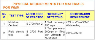
➤Moisture content test as per IS 2720 Part-2 at a frequency of 1 test for every 250 cum at the time of spreading and rolling,
➤MDD and OMC  As per IS 2720 Part-8 at a frequency of 2 test per 3000 cum,
➤Laboratory determination of CBR as per IS 2720 Part-16 as required,
➤Atterberg’s limits at a frequency of 1 test per 200 cum,
➤Field Density test as per IS 2720 Part-28 at a frequency a set of test for every 1000 sqm to a minimum of 6 tests up to 3000 sqm, if nuclear density meter is used the frequency shall be doubled,
 

PROBLEMS AND REMEDIES IN GSB CONSTRUCTION

 
PROBLEMS REMEDIES 
➤ GSB bed compaction less than required

➤Variation in surface level

➤Over burden materials mixed during preparation of GSB material,

➤Approved GSB bed

➤GSB Material Dumped Over moist or Wet Surface

➤Required Compaction should not be less than 98 %,
poor Compaction may lead to settlement
➤surface level tolerance limits:➯
for Sub grade:- +/- 20 mm,
for GSB        :- +/- 10 mm,
The Surface level shall be maintained within the tolerance limits else may impact of required thickness of next layer,
Rework may occur due to unacceptable tolerance,
➤Gradation:➯ specified gradation as per approved design
Liquid limit and Plasticity Index:➯ Max 25 And max. 6,
In such case, specified gradation and plasticity index limit shall be ensured before loading the GSB materials or at least before spreading.
Chances of Impact on the drainage properties,
➤At actual completely disturbed bed due to the following reasons,
➯Poorly Graded ⟶ Leads To Segregation,
➯Poor Workmanship⟶after final grading it would have rectified,
➯Poor Quality Control⟶before testing it would have suggested to concerned site Engineer to rectify the bed which leads poor compaction and segregation,
100 % Rework Required
➤Moisture Content ⟶OMC +1% and OMC -2%
➱The bed Should Have moisture Content as per requirement before proceeding for the next layer,
➱Rework may occur due to improper supervision
➱settlement of successive layer
 
Click here for More Working Procedures and Engineering jobs


WET MIX MACADAM CONSTRUCTION-WMM CONSTRUCTION

Wet Mix Macadam (WMM)

WET MIX MACADAM CONSTRUCTION-WMM CONSTRUCTION

 
WET MIX MACADAM CONSTRUCTION-WMM CONSTRUCTION
WET MIX MACADAM CONSTRUCTION


WET MIX MACADAM CONSTRUCTION

WET MIX MACADAM – INTRODUCTION

Wet Mix Macadam (WMM) Consist Of Laying And Compacting Clean, Crushed Graded
Aggregate Granular Material, Premixed With Water To a dense mass on Prepared
Sub Grade/Subbase/Base,


What is wet mix macadam?
What is full form of WMM?

FUNCTIONS OF WET MIX MACADAM (WMM)

It
Acts As A Binding Layer Between the Granular Sub Base ( GSB) And The Bituminous
Layer, Provides Structural Support to The Pavement And Helps Dispersing Traffic
Loads To The Layers Below,
 
 
It
Is An Improvement Over the Conventional Water Bound Macadam (WBM) Layer Because It
Has A Superior Gradation Of Aggregates, a Faster Rate Of Construction, Less
Consumption Of Water, High Standard Of Densification And Higher Standard of
Quality Achievable,


What is difference between WMM and WBM?
Why WMM is used?


MATERIAL REQUIREMENTS FOR WET MIX MACADAM (WMM)

➤Crushed Stone,
➤If Crushed Gravel/Shingle Is Used Not Less Than 90 % of Its Weight Retained on 4.75 mm Sieve Shall Have At Least Two Fractured Faces,
➤Binders Such As Lime Stone Dust, Kankar Dust,
➤Screeners Such As Moorum, Crushed Over Burnt Bricks etc,
➤Shall Satisfy the grading Requirements as will be explained Shortly Please Continue to Read,
➤Shall Satisfy the physical Requirements as will be taken up Shortly Please Continue to Read,

GRADING REQUIREMENTS OF MATERIALS( in image below)

 
WET MIX MACADAM CONSTRUCTION MATERIALS
wet mix macadam aggregates

PHYSICAL REQUIREMENTS OF MATERIALS( in image below)

WET MIX MACADAM CONSTRUCTION
 
WET MIX MACADAM CONSTRUCTION
WET MIX MACADAM MATERIALS PHYSICAL REQUIREMENTS

MACHINERY REQUIREMENTS FOR WMM CONSTRUCTION

Following Machines are Required For Wet Mix Macadam Construction
 
 
WET MIX MACADAM CONSTRUCTION-WMM CONSTRUCTION
Machines for WMM Construction


CONSTRUCTION OPERATION AT WET MIX MACADAM PLANT

MIXING OF WMM-

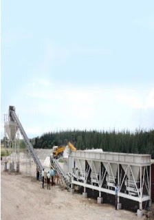
➤The Coarse Aggregates, Fine Aggregates And Water Shall be Mixed In The Mixing Plant, Which Shall Have a mill of Suitable Capacity For Mixing,
 
➤The Plant Shall Have Different bin feeders for Different fractions Of Aggregates, Required to Arrive at the Required Gradation,
 
➤ A controlled water addition Mechanism shall be present to give a continuous flow of mixed material that suits pavement requirements at the site,
 
➤The individual fraction shall be loaded to the bins of the mixing plant by front-end wheel loader tippers from the stockyard,
 
➤Care shall be taken at the stockyard and at the bin feeders to ensure that the aggregate should not be contaminated or mixed with other fractions,
 
➤The aggregate for the bottom 100 mm thick of the stockpile shall not be fed in the plant bin,
WET MIX MACADAM CONSTRUCTION-WMM CONSTRUCTION
WMM PLANT

What is wet mix plant?

How is Wmm prepared?
What is WBM?
What is water bound macadam?
 

CONSTRUCTION OPERATION OF WMM WITH GRADER

➤The Toe line/fixing of pegs to mark the limits of the WMM level shall be done before the commencement of work,
 
➤The Width of Pavements for the Toe line shall be calculated by referring drawing with due consideration to formation width plus the offsets and slopes of different layers’ depth of the current layer from the formation road level (FRL),

What is the WMM layer?

HAULING AND DUMPING-

➤The Required Quantity Of Wet Mix Macadam(WMM) Shall Be Calculated and Informed To WMM Plant Engineer Of Staff Whoever is taking care of Production,
 
➤Dumping Pattern Such as to ensure uniform spread, shall be determined and explained to the person who is taking care of dumping at the site,
 
➤The Material for WMM shall be hauled to the site by tippers and dumped on the bed in a predetermined pattern,

SPREADING AND GRADING-

➤The Materials shall be mechanically (grader etc.) spread in uniform layers such that compacted thickness not exceeding 200 mm or any other specified with due considerations to the loose thickness (Compaction Factor) of WMM,
 
➤Control pegs at every 10 m long C/L shall be fixed on both sides of the bed in such a manner that they are not disturbed by grader movement,
 
➤Required Levels shall be marked on the pegs with suitable vertical offsets,
 
➤After rough initial spreading, a cotton/nylon string (line door) shall be held at marks on the control pegs at both sides,
 
WET MIX MACADAM CONSTRUCTION
WMM level fixing 
 
 
WET MIX MACADAM CONSTRUCTION
WMM Spreading And leveling with grader

CONSTRUCTION OPERATION OF WET MIX MACADAM WITH PAVER

WET MIX MACADAM CONSTRUCTION-WMM CONSTRUCTION
WMM Laying with Paver

SPREADING/LAYING WITH PAVER –

➤Immediately after mixing WMM shall be transported to the laying site by tippers and shall be spread uniformly and evenly upon the prepared first layer of WMM or GSB layer with the help of a paver finisher,
 
➤However at the time of spreading the surface shall be checked for grade, camber and thickness with templates and high or low spots are to be rectified by removing or adding fresh material of the same properties,
 

JOINT PREPARATION-

➤The work shall be planned in a manner to reduce the number of joints to the minimum. A full-width paver shall be used, if possible, to avoid longitudinal joints,
 

LONGITUDINAL JOINT-

➤Rolling Shall be done on a strip of approximately 150 mm to 200 mm width from the edge on which the joint is expected to come,
 
➤This strip shall be rolled along with the edge of the next paver pass,
 
➤Rolling shall be done in such a manner that the roller drum moves on both the previous and the new surface,
 
➤The evenness of the joint shall be checked by a straight edge and rectification, if any shall be done immediately,
 

TRANSVERSE JOINT-

➤A straight edge shall be kept over the transverse edge of the previous work in such a manner that half of the straight edge is on the old surface and another half hangs towards the side where new work has to be carried out,
 
➤Marks shall be given on the points from where the surface level has started coming down,
 
➤The old surface shall be cut from the points marked above and removed. the cut material can be reused,
 
➤After the paver has passed over the joint the new surface near the joint shall be trimmed and shaped slightly as required,
 
➤Roller shall transversely run over the joint in such a manner that the roller drum moves on both the previous and new surface,
 
➤ The evenness of the joint shall be checked by a straight edge and rectification, if any shall be done immediately,
 
WET MIX MACADAM CONSTRUCTION-WMM CONSTRUCTION
transverse joint WMM Laying With Paver

QUALITY CONTROL TESTS AND THEIR FREQUENCY

➤Gradation at a frequency of  test for every 100 cum,
 
➤Atterberg berg limits at a frequency of  test for every 100 cum,
 
➤MDD and OMC As per IS 2720 Part-8 at 1 test for Source,
 
➤Combined Flakiness and Elongation index 1 test for every 200 cum,
 
➤Aggregate impact value At a frequency of 1 test for every 200 cum,
 
➤Water absorption at a frequency of 1 test for source,
 
➤Density of Compacted layer at 1 test(6 pits)/500 sqm and 1 pit for an additional 50 sqm or less,
 
➤ Top-level checking for given stretch,
 

PROBLEMS IN THE CONSTRUCTION OF WMM LAYER AND REMEDIES TAKEN

PROBLEMS REMEDIES
➤Availability of WMM plant in good Condition,
➤Mix gradation

➤Thickness and levels of the layers

➤Compaction and Workmanship

➤Confinement

➤Segregation of the mix

➤Plant should be in good condition, with regular maintenance,
➤Ensure gradation of mix before dispatching the mix,
➤Ensure The proper level of GSB before laying of WMM,
➤Ensure 98% Compaction and Good Workmanship,
➤Ensure Laying of Adjoining shoulders along With WMM,
➤Inform the Immediately if mix is not proper and rectify the segregation at the site, 


Click here for more Other Updates and work procedures
Click here for engineering jobs


Delhi – Vadodara Expressway Pkg-22,

Delhi - Vadodara Expressway Pkg-22,
Delhi Mumbai Expressway 

Delhi-Vadodara Expressway


About The Project- Delhi-Vadodara Expressway Is Going To Be The Longest Expressway In India After Completion Of It’s Construction Work, It Will Connect To Mumbai The Commercial Capital Of India Also That’s Why It is Named As Delhi-Mumbai Expressway as well,

Foundation Stone Was Laid By Union Ministers Sushma Swaraj , Arun Jaitely And Nitin GadKari On 8th March 2019,

This Expressway Will Be Constructed In 8 Lanes With Median Separator As per NHAI Requirements, It Will Reduce The Travel Time Between Delhi To Mumbai By 24 Hours To 12 Hours,

Delhi-Mumbai Expressway Project Is Divided Into 34 Stretches ( Packages) For Construction To Reduce The Construction Time And Budget,

Mumbai Vadodara Expressway 

Delhi Jaipur Expressway

Locations Of Project- Delhi-Vadodara Expressway Or Delhi-Mumbai Is Going Through The Major Backward Areas Of Delhi , Haryana , Rajsthan , Madhya Pradesh ,Gujrat And Maharastra,

Total Cost Of Project- The Estimated Construction Cost Of Delhi -Vadodara(Delhi -Vadodar-Mumbai) Expressway Project Is 90000 Crore,

About Delhi-Vadodara Expressway Package 22

Delhi-Vadodara  Expressway Is being Constructed In Many Packages The Reduce Its Construction Time And To Minimize The cost, Package 22 Is The Part of  Delhi – Vadodara Expressway,


Starting Point- Kandarwasa (Ratlam district)

End Point- Bawadi Village- Near Shivgarh (Ratlam district)

Total Length- 25 kilometers,

Total Cost- 1022 Crore,

Bid Submission Date- 29-01-2020,


Bid Opening Date- 08-05-2020,

All Companies Filled The Tender Form- Many  Companies Has Shown It’s Interest For Construction Of Delhi-Vadodara Expressway, List Of Few Companies With There Bidding Amount Are As Below,

Delhi Vadodara Expressway Contractors ?,

Larsen and Toubro Limited- 993.007 Crore (L-1)
GHV- 999.22 Crore,
Ashoka- 1008 Crore,
JIANGXI- 1033.60 Crore,
Tata – 1047 Crore,
NCC- 1080 Crore,
GR Infra – 1087.77 Crore,
Dilip Buildcon -1120.05 Crore,
Sadbhav – 1152 crore,
Gayatri – 1172 Crore,
MonteCarlo – 1172.2 Crore,
DRA – 1377.41 Crore,
CREC- VARAHA JV- Disqualified,
GGHB- Disqualified,

Lowest Bidder Company- The Lowest Bidder Company For Delhi- Vadodara Expressway Pkg 22 Is Larsen And Toubro Limited, The Tender Value Filled By Larsen And Toubro Limited Is 993.007 Crore, Second Lowest Bidder For Pkg 22 Is GHV With 999.22 Crore Tender Value,

About The L-1 Company- Larsen And Toubro Limited Is An Indian Multinational Company, L&T Is One Of The Major Engineering , Construction, Technology ,Manufacturing , And Financial Services Conglomerate With Global operations , It Is Engaged Over 30 Countries Worldwide In Construction, Engineering , Manufacturing And Other Operations, It’s Revenue Is Over 21 billion USD,


Click Here For More Results,

Click Here For Current Govt Jobs

Test Of Cement – Consistency Test

Test Of Cement – Consistency Test

Test Of Cement – Consistency Test

Test Of Cement - Consistency Test
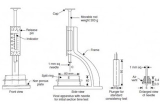
Test Of Cement – Consistency Test Apparatus
 

Purpose Determination Of Consistency For Cement

The test Of Cement – Consistency Test Is Done To Find Out The Consistency Of Cement Which Permits The Vicat apparatus Plunger To Penetrate to a point 5 to 7 mm from the bottom of the Vicat mould when tested. The procedure to determine the quantity of water required to produce a cement paste of standard consistency is Explained In the Following Steps.
 

Reference Code For Determination Of Consistency Of Cement

 
Determination Of Consistency Of Cement Is Done According To IS Code 4031 (Part 4).
 

Required Apparatus For Determination Of Consistency Test


1- Vicat Apparatus With Mould

 
The vicat apparatus consists of a frame having a movable rod with a cap at one end and at the other end any one of the following attachment, which are interchangeable.
Test Of Cement - Consistency Test
Test Of Cement – Consistency Test apparatus


2- Needles

 
There Two Types Of Needle Are Required For First For Initial Setting Time And Second For Final Setting Time,
 
For Initial Setting Time- The needle is having a cross sectional area of 1mm2. The end of the needle is flat.
 
For Final Setting Time- The needle is circular having a cross sectional area of 1mm2. The needle is fitted with a metal attachment. The end of the needle projects beyond the cutting edge of the hollowed out metal attachment.
 

3- Balance

 
Electric Or Any Other Balance Is Required With Highly Precision To Measure The Weight Of Cement,
Test Of Cement - Consistency Test
Electric Balance
 

4- Plunger for Standard Consistency Test

 
It is made of polished brass 10 ± 0.05mm in diameter with a projection at the upper end for insertion into the movable rod. The lower end is flat.
 

5- Graduated Scale

 
Graduated scale is 40mm in length and the smallest division of scale is 1mm.
 

6- Vicat Mould

 
The vicat mould is in the foam of a frustum of a cone having an internal diameter of 60+/- 0.5 mm at the top, 70 +/- 0.5 mm at the bottom and height 40 +/_ 0.5 mm.


The split type vicat mould is used as an alternative to single mould. This mould consist of a split ring having an internal diameter 80+/- 0.1mm and a height 40+/_0.5mm. A non-porous base plate is provided. The split mould is provided with a suitable clamping ring.


7- Standard Weights


8- Gauging Trowel


9- Non Porous plate


Detailed Standard Operating Procedure (Test Of Cement – Consistency Test)


>   Take 500 gms Of Cement.>   Add 24 % Water Into Cement.>   The Paste Must Be Prepared In A Standard Manner And Filled Into Vicat Mould Within 3 To 5 Minutes.>   After Filling The mould Shake The Mould To Expel Air.
>   A standard Plunger is Brought Down To Touch The Surface of the Paste In The test Block And Quickly Released Allowing it To Sink Into Paste By It’s Own Weight.
>   Take The Reading And Note Down It.
>   Conduct The Second Trial With % Of Water At 25 And Take The Reading
>   Conduct Similar Trials With Higher W/C Ratio Till Plunger Penetrates For A Depth Of 33 to 35 mm From The Top.
>   The Percentage Of Water At Which Penetration 33 to 35 mm From To Top Or 5 to 7 mm From Bottom Is A standard Consistency.

Click Here For Updates on Current Engineering Jobs


Click Here For Other Government Jobs Information